Battery and Energy Technologies |
|
Boolean Logic and Digital Circuits
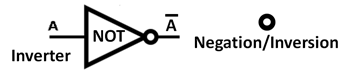
Modern digital computers are built from digital logic circuits whose basic building blocks are logic gates, each of which is designed to implement a specific logical function. Information is held in data "words", representing data or instructions, made up from strings of individual "bits" with binary values of 1 or 0. These values are analogous to Boolean logic propositions and the statements or conclusions derived from them which were defined as "true" or "false". Boolean algebra is the tool used to design combinations of gates to implement more complex functions such as mathematical operations, control functions and data storage. Boolean AlgebraBoolean algebra is based upon a two-valued, or binary scheme. The two values may be expressed in many ways, such as true or false, 1 or 0, and "on" or "off". It is this property which was recognised and developed by Claude Shannon in 1937 which makes it so useful for implementing logic functions by means of electronic circuits. For example, logic 1 and logic 0 might be implemented as two different voltage levels in a circuit, or by the status of a switch, or by the presence or absence of a current in the circuit. Notation The engineering application of Boole's logic uses a simplified version of the original notation as follows,
It can represent parallel switch contacts. It can represent series switch contacts. Note that it has become conventional to drop the dot . sign (AND symbol) so that A.B is written as AB. It can represent normally closed switch contacts.
Boolean Laws
Commutative Law
Associate Law
Distributive Law
Identity Laws
Redundance Laws
Involution Law
De Morgan's Theorem
In addition to the above Boolean algebra, digital logic gates have been developed to represent Exclusive OR and Exclusive NOR expressions extending the original range of Boolean laws. See exclusive OR expressions below. Logic GatesLogic gates may have two or more inputs and, except in some special cases, they have a single output. The status of the input and output terminals can only be in one of the two binary conditions, either low (0) or high (1), represented by two different voltage levels, typically 0 volts for logic 0, and around 3 to 5 volts for logic 1, depending on the semiconductor technology used. Logic gates also require a power supply. The Transistor as a SwitchElectronic gates are generally constructed from transistor circuits which depend for their operation on the use of the transistor as a switch, rather than as an amplifier for which it was originally invented. With no voltage on the base, there is no current through the transistor which is thus switched off and the output (collector) voltage will be high. When a "high" voltage is applied to the base the transistor is switched on and output (collector) voltage will be "low". See more on the page about semiconductors.
XOR and XNOR GatesThe Exclusive OR (XOR) gate with inputs A and B implements the logical expression
The Exclusive NOR (XNOR) gate with inputs A and B implements the logical expression
Exclusive OR gates are commonly used for comparisons and parity checks.
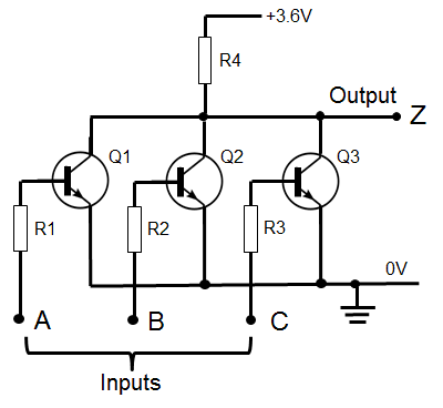
Three Input NOR Gate
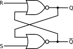
Digital Logic CircuitsBoolean logic is used to design complex digital circuits to perform a wide variety of logical functions. There is however often more than one way to implement a logic circuit by using alternative types of gates. Some examples follow. Set-Reset Flip-Flops and Latches
Registers are common storage devices providing temporary storage of multi-bit data words such as 4, 8 or 16 bit words. They are constructed from groups of flip-flops each storing a single bit of information so that n flip-flops are used to store an n bit word. Adders
Full adders are designed to accept a carry bit from a previous stage and hence have three inputs. The circuit below is a an example of single bit, full adder constructed entirely from two input NOR gates. In this case it is essentially two, two-input, half adders in series with the input carry bit bypassing the first adder and being added to the sum of the two input bits from the first adder, in the second adder. Note that it takes 12 such gates simply to add two single bits plus any input carry bit from a previous addition stage and to provide two output bits representing the sum of the bits and any associated carry bit. A logic circuit designed to add two eight bit words will require eight times as many gates.
It may seem strange to use so many gates when the circuit could easily be implemented with fewer, more complex gates, but circuits such as the adder above were used in the Apollo Guidance Computer which took the US astronauts to the Moon in 1969. All of its digital circuits were built from three input NOR gates. This was because they needed highly reliable semiconductor components and at the time (1966) when the computer design was frozen, integrated circuit technology was still in its infancy and NASA wanted to limit the number of different components used to those which had a proven track record. NOR gates were chosen because they were one of the very few options that met this requirement and because NOR gates were simple and more versatile than other available gates for building more complex functions. Binary ArithmeticA binary adder can be adapted to perform other arithmetic operations such a subtract, multiply and divide as well as other more complex mathematical functions, avoiding the need for multiple specialist processors, by making use of the following principles of binary arithmetic.
The following are three of the most common examples.
To subtract binary number B (the subtrahend) from binary number A (the minuend). This involves n steps where n is the number of bits in the multiplier. The first Step In each subsequent step: This operation involves m-n steps where m is the number of bits in the dividend (the number being divided) and n is the number of bits in the divisor. Note: Checks must be included and the operation set up to avoid the potential problem of dividing by 0.
In each subsequent step: The subroutines include special check points to detect and insert extra instructions to deal with carry and borrow bits, overflows, negative numbers, remainders, divide by zero whether the divisor is greater than the dividend. Subroutines similar to those above, in combination Boolean logic circuits, are used to enhance the capability of the computer's Arithmetic Logic Unit (ALU) to enable it to carry out many more complex functions. See more about Computer Architecture Floating Point ArithmeticThe computer's calculating unit has just two hardware tools in its tool bag, "shift" and "add" to carry out all its mathematical operations. The basic four function arithmetic operations, outlined in the foregoing section, were all carried out with these two tools and all concerned operations on integer numbers. However in practical applications, even the most simple mathematical calculations involve operating with decimal numbers. Besides this, the computer may also be required to handle transcendental functions such as logarithms, exponential and trigonometric functions which can not be represented by simple algebraic expressions and can thus not be processed by the computer's simple shift and add capability. Transcendental functions can however be expanded and expressed as an infinite series of simpler algebraic expressions each of which can be processed by the machine's basic operations but summing an infinite series is not practical. Some form of mathematical approximation is required. Fortunately, the initial algebraic terms of the series usually, but not always, converge quickly down to very small values such that subsequent terms can safely be ignored without seriously affecting the accuracy of the result. Thus the transcendental function can be considered as a polynomial consisting of just the first few significant terms in the series. See examples (below) In addition to the problem of precision, there's also the problem of scale. It is difficult to manage both very large and very small numbers in computer data registers and communications buses of practical size. Some examples:
These last two numbers may even appear in the same equation. The size problem is even more difficult when the numbers are represented in their much longer binary form. The use of conventional scientific notation solves part of this problem but introduces the need to manipulate the position of the decimal point. These problems of accuracy, precision and scale are solved by the use of floating point arithmetic which uses the more convenient scientific notation but calculation methods are still limited to the computer's basic shift and add capability. These basic operations can however be augmented by software subroutines and extra logic and registers to store temporary or intermediate values. The following are some examples of floating point calculations: First some definitions: Number Definitions
Also called the Significand, contains all the number's digits. Negative significands represent negative numbers. (Beware that the term "mantissa" may cause confusion because it can also refer to the fractional part of the common logarithm.) The reference number on which the exponent is based. It is the power to which the base is raised. It indicates where the decimal (or binary) point is placed relative to the beginning of the significand. The binary equivalent to the decimal point in decimal numbers. Example In scientific notation the decimal number 345.6 can be represented by 3.456 X 10² where 3456 is the mantissa or significand, 10 is the base and 2 is the exponent. Floating Point Number Benefits
Floating Point (FP) Operations Floating point operations can be implemented by hardware (circuitry) or by software (program code). Software is however much slower than hardware by two or three orders of magnitude. Bit Shifting Shifting the mantissa left by 1 bit decreases the exponent by 1 and moves the radix point right by one place. Shifting the mantissa right by 1 bit increases the exponent by 1 and moved the radix left by one place. Basic FP Algebraic Functions
Transcendental and Other Functions It is possible, but not necessarily practical, to store all the required values of transcendental functions in look-up tables stored in the computer's memory. While this would be convenient, in many applications however, it would require impractically large memories. Instead the necessary values must be calculated as required. Estimating the value of a transcendental function involves setting up a loop to calculate the value of each significant term in the series in turn, and summing the values in a separate accumulator (taking the sign into account). The more the terms in the series, the better will be the accuracy, but the processing time will be correspondingly longer due to the increased number of calculations. It is often possible to represent the transcendental function using alternative mathematical approximation methods. As in the trade-off between speed and accuracy above, the alternative methods also involve similar trade-offs. The Taylor series is a common mathematical expansion, though not the only one, used to approximate the value of transcendental functions. Some typical examples using the Taylor series follow. See more about the Taylor series. See also the CORDIC expansion (below).
Note that these two series involve both positive an negative terms and the denominators involve increasing factorials. This means that the terms will converge very quickly to small magnitudes. Note also that the computer does not usually calculate the numerical values of the factorials which are instead retrieved from look-up tables in the memory. An alternative to the Taylor series for estimating the value of the sine function is the Hastings approximation which is about three times faster and only slightly less accurate. The function is divided into a small number of intervals and, in each of these, a straight line approximation is used. The slopes of the straight line segments have denominators which are powers of 2, and so the calculation does not need floating point multiplication or division operations. This was the algorithm used for trigonometric calculations in the Apollo 11 Guidance Computer which took the astronauts to the Moon.
This is valid for any real number Z that satisfies 0 < Z < 2.
Note that all the terms in this series are positive and the numerators increase more quickly than the denominators so that the series does not converge but expands. The square root is not a transcendental function. Numerous ways for calculating square roots have been developed since the first formal method was proposed by the Greek mathematician Hero of Alexandria in the first century A.D. The simple method based on "guess, check and refine" has been used for many years. It works as follows where a is the desired square root √x The magnitude of E will progressively decrease until the desired accuracy is reached. This method was designed for use with decimal numbers. It is not so convenient with binary numbers and can lead to an excessive number of loops to converge on an acceptable answer. Extra steps in this simple program can improve this. The square root can be calculated directly by using the properties of natural or base 10 logarithms but the logarithms themselves are transcendental functions and the values must first be extracted from a suitable approximation routine such as the one above. The method depends on the following properties of the natural logarithm (ln): and The answer is given by: √x = e(ln X)/2 using the natural logarithm (ln) Alternatively, using the base 10 logarithm (log), the answer is given by: √x = 10 e(log X)/2 (Dividing the exponent by 2 generates a square root, the same as with logarithmic tables). Pocket calculators typically use this method of calculating square roots. CORDIC Approximation Algorithms The CORDIC algorithm is an iterative method for calculating transcendental functions using only binary shift and add operations. Using the example of calculating the value of a tangent, X/Y = tan Θ, expressed in the form tan(2-n) A vector from the origin (zero) is rotated in a series of "n" small steps δΘ so that the sum of all the steps is equal to Θ. By accumulating the corresponding changes in the values of its orthogonal coordinates δX and δY at each step, the values of X and Y and hence the tangent can be calculated. Described by J.E. Volder in 1959, the CORDIC algorithm was used in the first scientific hand-held calculator (the HP-35) and variations of this simple basic concept have since been developed and refined for approximating a wide variety of transcendental functions.
|
|||||||||||||||||||||||||||||||||||||||||||||||||||||||||||||||||||||||||||||||||||||||||||||||||||||||||||||||||||||||||||||||||||||||||||||||||||||||||||||||||||||||||||||||||||||||||||||||||||||||||||||||||||||||||||||||||||||||||||||||||||||||||||||||||||||||||||||||||||||||||||||||||||||||||||||||||||||||||||||||||||||||||||||||||||||||||||||||||||||||||||||||||||||||||||||||||||||||||||||||||||||||||||


![]() Print This Page || Home || FAQ || Site Map || Legal || Privacy Promise || Contacts
Print This Page || Home || FAQ || Site Map || Legal || Privacy Promise || Contacts
Woodbank Communications Ltd, South Crescent Road, Chester, CH4 7AU, (United Kingdom)
Copyright © Woodbank Communications Ltd 2005
