Battery and Energy Technologies |
|
Hydrogen Fuelled Electricity Generation
The Hydrogen EconomyHydrogen is being promoted as the perfect environmentally friendly fuel of the future.
What many "Hydrogen economists" don't make clear is - Where will the energy come from to extract the hydrogen from the water? Hydrogen is an energy carrier, not an energy source, so the energy it delivers would ultimately have to be provided by a conventional power plant.
This page considers some of the issues.
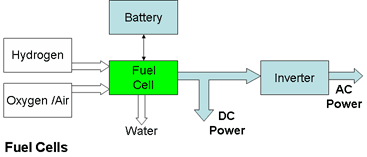
Fuel CellsThe fuel cell was invented in 1839 by Welsh lawyer Sir William Robert Grove. It takes in Hydrogen and Oxygen from the air and puts out electricity, heat, and water. It doesn't use fossil fuels and it doesn't produce greenhouse gases and so it should be the ideal solution to providing distributed or portable electrical power. Despite its obvious advantages it was not until the 1950s in response to the needs of the US space programme that practical devices were developed. Even today, although there are many variants of fuel cells working in development labs throughout the world and small scale deployment of demonstration units in some countries, there is still no volume production. What is holding back the commercialisation of fuel cells?
The following diagram shows the key system components for providing AC or DC power.
But this diagram only tells part of the story. Though the basic principle is quite simple, converting this into a practical product involves many engineering challenges and up to now the solutions proposed have not been cost effective. Fuel cells are an expensive way of providing electrical energy. The prize of cheap, clean, renewable energy is still unclaimed but engineers are getting ever closer to winning it. The following section describes their tasks and the current state of development.
Fuel cells don't store energy like batteries. They only provide electrical energy while the active chemicals are supplied to the electrodes. The process is described in more detail in the two examples below.
Proton Exchange Membrane (PEM) Fuel Cell The most common fuel cells use Hydrogen as the fuel and Oxygen from the air as the oxidant. The basic reaction can be illustrated by the Proton Exchange Membrane (PEM) fuel cell. (Also called the Polymer Electrolyte Membrane fuel cell.)
The overall equation for the reaction is 2H2 + O2 ⇒ 2H2O The equation for the reactions at the individual electrodes are shown where they take place on the diagram below.
The electrodes are made from porous carbon which allows the active gases to pass through and the electrode surfaces support platinum catalysts.
The electrolyte is a thin, fragile sheet of acidic, solid organic polymer about 50 microns (2 thousandths of an inch) thick which permits the passage of Hydrogen ions but is impermeable to electrons. Acidic compounds are fluids with free Hydrogen ions and these are the fuel cell's charge carriers.
The Hydrogen is supplied to the anode where it is oxidised losing electrodes in the process. The positive Hydrogen ions (protons) migrate across the electrolyte through the membrane to the anode while at the same time the electrons travel round the external circuit to the cathode. The Oxygen is supplied to the cathode where it is reduced, picking up the electrons and the ions from the Hydrogen to form water.
The electron flow between the anode and the cathode caused by the chemical reactions in the cell represents the conventional electrical current flowing in the opposite direction. This electrical current is available to do work in the external circuit.
Catalysts are needed to increase the rate of oxidation at the anode and the rate of reduction at the cathode. In this way they allow the chemical reaction to take place at a lower temperature. Alternatively to avoid the cost of expensive catalysts, some fuel cells are designed to work at elevated temperatures. The platinum catalyst used in PEM and some other cells is very expensive and extremely sensitive to poisoning by even small amounts of Carbon Monoxide making it necessary to employ an additional filtering processes in the system to eliminate potential contaminants.
Direct Methanol Fuel Cells (DMFC) Early PEM and Phosphoric Acid electrolyte Fuel Cells (PAFC) fuel cells employed an external steam reformer (See below) to generate the local Hydrogen supplies using Methanol as the fuel. Recent fuel cell developments have however eliminated the reforming process by feeding Methanol instead of Hydrogen directly into the fuel cell. Unfortunately Methanol is toxic.
The working of the direct Methanol fuel cell is similar to the PEM fuel cell shown in the diagram above. The electrolyte is a polymer and the charge carriers are the hydrogen ions. Liquid Methanol (CH3OH) is fed into the anode of the cell where it is oxidized in the presence of water generating Carbon Dioxide (CO2). The cathode chemistry is the same as in the PEM cell with the Oxygen combining with the Hydrogen ions and electrons from the external circuit to produce water. The reactions are as follows:
Like PEM fuel cells DMFCs work at low operating temperatures in the range from about 50ºC to 120ºC but they have a relatively low efficiency and power density. Output power using current technology is limited to about 1.5 kW which enough to power most consumer goods but insufficient for automotive applications which require much higher power.
Nevertheless the ability to use liquid fuel coupled with the elimination of the reformer make these fuel cells very attractive.
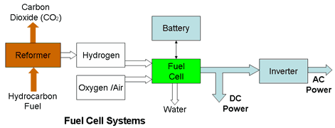
Balance of Plant (BOP) The fuel cell stack alone can not generate electricity. Practical systems need sub-systems to supply the fuel and to provide the necessary control over the processes involved in the energy conversion. The essential ancillary equipment , the so called "balance of plant", can be just as expensive and complex as the fuel cell stack itself. Some of this equipment is outlined in the following list;
The largest item is the reformer (See below) which provides local generation of the Hydrogen fuel. The reformer itself must have storage capacity for the reformate fuel used in the process. If Hydrogen generation is not part of the system, there must be some form of storage to carry the Hydrogen fuel to be consumed by the fuel cell. This requires expensive high pressure tanks or cryogenic storage tanks (See also below) Pumps are needed to pump the reactant air through the stack and to provide forced cooling. Higher power systems require compressors to handle the higher airflow rates. Expanders are needed to reduce the high pressure of the stored Hydrogen to the required input pressure at the stack. Filters are needed to remove any contaminants from the fuel supplies which could poison the catalysts or damage the cells reducing their power production and ultimately causing their shut down. Particular offenders are Carbon Monoxide, resulting from incomplete reactions in the reformer, which affects the platinum catalysts and Sulphur found in reformates derived from fossil fuels, such as coal, oil, and natural gas, which contaminates the Hydrogen gas and in turn attacks and degrades the anodes. High power systems use forced cooling with fluid coolants to remove the heat. This requires fluid pumps and a radiator/heat exchanger to expel the heat. The system also requires heaters to bring the stack temperature up to its operating point on start up. An overall thermal management system is required to balance the heat flows to keep the temperature of the stack at its optimum operating point. The conductivity of the electrolyte in the cell is proportional to the water content and it must be kept moist to remain conductive. The airflow and the heat generation in the cell tend to work against this. Consequently the air supplied to the cell must be humidified to stop electrolyte drying out and this requires a humidifier. Cold temperature operation in freezing conditions also brings problems due to the formation of ice crystals which can damage the electrolyte or membrane. The system must incorporate a method of purging the water or alternative anti-freeze controls. Another pump may be required to remove surplus water from the cathode. Though some fuel cells may be required to provide a steady operating current and voltage, most systems must be responsive to variable demands. This means that the system should provide for a variable output current and as a consequence, all the fuel, air and water flows must be varied accordingly. At the same time the heat dissipation will change and the temperature must be maintained within its designed operating range. The same will apply to the reformer if this is part of the system. The fuel cell system output voltage is fixed but the application may require a different voltage or, in the case of most distributed power generators, an alternating current output. In these cases DC/DC converters or AC inverters may be an integral part of the system. Motors of different sizes are required to drive the pumps and compressors. Sensors are required to monitor temperatures, pressures, fluid and gas flows as well as electrical currents and voltages. The fuel cell does not start to deliver electrical energy until it approaches its operating point. During start up, batteries are required to power all the electronic control systems, as well as the pumps, compressors and heaters needed to get the stack up to its operating point. The battery also provides an independent stable voltage to power the system electronics. Because of the slow dynamic performance of the fuel cell, the battery may also be required to provide a temporary power boost when the fuel cell is subject to a sudden demand. Safety systems must provide fail safe operation, protecting the system from out of tolerance conditions and abuse and shutting it down if necessary. The system could not function without comprehensive electronic control systems to manage all the sub-systems listed above.
Electrical Output
Fuel cells typically generate about 0.6 Volts to 0.9 Volts DC per cell. Due to the internal impedance and losses within the cell, the output voltage falls as the current is increased. Multiple cells in a stack must be used to provide higher voltages.
The current output from a single cell is directly proportional to the area of the electrodes. As with batteries the effective area of the electrodes and hence their potential current carrying capability can be increased without increasing their physical size by making the surface porous and using materials with very fine particle size. Typical power outputs are about 1 Watt /cm2 of electrode plates.
Fuel Cell Variants A range of fuel cell designs using variants of the basic chemistry has been developed to meet different design or operating criteria such as less expensive construction, more efficient fuel utilisation, faster start-ups or the use of more convenient or less expensive fuels. Higher power outputs can be achieved by operating at high temperatures, by using catalysts to accelerate the fuel cell chemical reaction and by using electrodes with a greater surface area. Lower operating temperatures can be obtained by using more expensive catalysts.
The main variants are as follows:
Proton Exchange Membrane Fuel Cells follow the basic design described above. They have a good combination of efficiency, power output and low operating temperature make it the cell of choice for automotive applications. Conversion efficiencies of up to 60% are possible. Though the maximum working temperature of most designs is 100°C to avoid damage to the fragile membrane, some products have been designed to work at temperatures up to 120°C.
Alkaline Fuel Cells use aqueous electrolytes of potassium hydroxide. They were some of the earliest practical cells and were used in the Apollo space programme, generating drinking water as well as electrical power. Although they are inexpensive compared with PEM cells, operating efficiencies of 60% are possible. Unfortunately they have a low power output and the catalyst is prone to poisoning from Carbon Dioxide in the atmosphere.
Phosphoric Acid electrolyte Fuel Cells run at a high temperatures of around 220°C delivering high power of a MegaWatt or more but a with relatively low efficiency of around 35%. The consequence of poor conversion efficiency is high heat generation in the fuel cell stack. Because of the high working temperature the efficiency losses can be mitigated by using the waste heat in combined heat and power (CHP) applications.
Molten Carbonate Fuel Cells run at even higher temperatures of 650°C to 1000°C. Their unique chemistry needs Carbon Dioxide from the air a part of the process. Efficiencies achieved are 45% or more and power outputs of over 1 MegaWatt are typical in grid supply applications. Because of their high working temperature they can operate directly with hydrocarbon gases which are reformed within the cell and do not need a separate Hydrogen supply. The high temperature also means that less expensive catalysts are needed, but the molten electrolyte imposes special requirements on containment and anti corrosion measures.
Solid Oxide Fuel Cells also operate in the same or higher temperatures as the molten carbonate cells with the same fuel and catalyst advantages. The ceramic electrolyte which can run as hot as 800 degrees Celsius has the advantage that the electrolyte stays solid. They can deliver powers of several Megawatts but at a lower efficiency of around 35%.
Direct Methanol Fuel Cells are similar to PEM cells but instead of pure Hydrogen they use inexpensive hydrocarbon liquid fuels avoiding the both the Hydrogen supply problems and the requirement for a local (or on board) reformer. They work at low temperatures of 50°C to 100 °C however the power output is low, limiting their possible applications to portable electronics equipment.
See also the Fuel Cell Comparison Chart for more details.
System Cost/kW Care must be exercised in comparing costs since some estimates may be for the fuel cell stack alone while others may include all the balance of plant costs which could double the cost.
Notes
Large systems providing distributed power generation are significantly more expensive than small systems used in automotive applications. Currently, costs are around $650/kW. The Solid State Energy Conversion Alliance (SECA) formed by the US Department of Energy to promote the development of environmentally friendly solid oxide fuel cells (SOFC) has a cost target for a solid-state fuel cell module of no more than $400/kW. At this price, fuel cells would compete with gas turbine and diesel generators.
Automotive ICE power plants currently cost about $25-35 / kW. A fuel cell system needs to cost less than $50 / kW for the technology to be competitive. Currently costs are around $70/kW. The US FreedomCAR project has set cost targets for PEM fuel cells at $45/kW by 2010 and $30/kW by 2015.
Fuel Costs The real cost of the energy supplied by fuel cells depends very much on the cost of the Hydrogen it consumes and this in turn depends on how the Hydrogen was produced.
Until recently, steam reformation of natural gas was the cheapest way of producing Hydrogen but production costs have risen with the cost of the fuel. Currently, assuming the cost of natural gas is about $10per M Btu (Million Btu) the bulk cost of Hydrogen at the production plant will be about $5/Kg. The cost of pressurising the gas and distribution it to refuelling stations will add to this amount. Generating Hydrogen by electrolysis from wind farm electricity is now the cheapest way of producing the gas.
Currently the retail price of pressurised hydrogen from an unsubsidised supplier is about $100/kg plus cylinder rental.
Practical Fuel Cell System Applications
Automotive Applications
Though concept models and prototypes which incorporate on board Hydrogen reformers have been produced, most recent offerings use gaseous Hydrogen in high pressure containers. Out of the total new fuel cell vehicles announced in 2005 and 2006, only 1 vehicle has not used a PEM stack with compressed hydrogen. PEM is the favoured technology because of its its high power output, its relatively low cost, its low operating temperature and fast start up.
Transient response time to increase the power output from 10% of rated power to 90% is 2 seconds. The cold start-up time to reach 50% of rated power is around 20 seconds The slow response to power demands could be dangerous in an automotive application. For this reason the fuel cell power must be augmented using energy stored in the battery or in supercapacitors.
Note that since the fuel cell can not store energy, it is unable to capture the energy recuperated from regenerative braking. This is another reason why automotive fuel cell systems need to incorporate batteries.
The current performance for passenger cars ranges from 40 to 60 miles per Kg of Hydrogen.
The US DOE EERE target lifetime for fuel cells is 5000 hours Currently a demonstrated lifetime of 2000 hours is the best achieved.
The lack of a distribution network has been one of the many factors which have hampered the commercial acceptance of Hydrogen power for automotive applications whether in fuel cells or by burning it in an internal combustion engine. Besides this, carrying around Hydrogen in high pressure containers was considered by some to be a safety hazard. For this reason on board Hydrogen generation using steam reformers was proposed and prototype systems were developed. Scaling down industrial steam reformers to provide reliable, low cost, portable systems proved very difficult and unfortunately, the expense of the reformer, its complexity and weight penalty outweighed the advantages of its freedom from the need for a Hydrogen infrastructure. Using a reformer in automotive applications is like carrying around your own chemical production plant to feed the vehicle's fuel cell. Furthermore, because of the reformer's CO2 exhaust gas, the vehicle can no longer be called Zero Emission Vehicle (ZEV). Apart from public relations considerations, it could also have tax implications in some countries.
For these reasons, pure Hydrogen is the chosen fuel for the current generation of Hydrogen powered vehicles. This means that the vehicles need to carry heavy and bulky Hydrogen storage containers. The choice is between high pressure containers and cryogenic containers. Because of the cost and complexity of the cryogenic solution, almost all fuel cell vehicles use the more economical high pressure containers. To carry sufficient fuel for a reasonable range of 200 to 300 miles, storage pressures of 35MPa (5000 psi) to 70MPa (10,000 psi) are required depending on vehicle design priorities (acceleration, speed, weight, payload etc).
Refuelling stations must be able to dispense Hydrogen at 70 Mpa to match the vehicle storage requirements.
Distributed Power Generation This application has been propose as a use for high capacity fuel cells. such installations need inverters to provide alternating current synchronised with the national grid.
The chemical reaction taking place in a fuel cell is an exothermic catalytic oxidation. The excess heat generated in high temperature fuel cells such as SOFC, PAFC and MCFC can be captured and used to heat water in a combined heat and power (CHP) application giving overall system efficiencies of 80% or more.
CHP is an ideal way of utilising waste heat from less efficient fuel cell electricity generators.
Burning Hydrogen in an Internal Combustion EngineWith minor modifications it is possible to replace petrol (gasoline) by Hydrogen as the fuel in an internal combustion engine. This has the major benefit of using well known, tried and tested power plant technology to reap the benefits of a zero emission power generation while avoiding all the technology risks, complications and expense of fuel cells.
Hydrogen powered internal combustion engines can already be found in emission free, traction (automotive) applications. The earliest examples were built in Germany by Rudolf Err en in the 1920s. Automotive engines can also be designed for multi-fuel use with the ability to use liquefied petroleum gas (LPG) or other fuels as well as Hydrogen. This could be an attractive option for early adopters of Hydrogen technology providing peace of mind on long journeys until a well developed network of Hydrogen dispensing stations has been installed.
Hydrogen powered internal combustion engines can also be used with rotary generators to generate electricity as shown in the following diagram:
Though this is perfectly viable, small, stand alone Hydrogen powered electricity generators are more likely to use fuel cells.
Hydrogen Fuel SupplyWhether the fuel cell application is static or portable, as in automotive applications, a constant supply of Hydrogen is needed to maintain the electrical output. There are two options, build a Hydrogen distribution infrastructure with refueling stations where gas can be dispensed, or generate the gas where it will be used. Hydrogen is produced at low pressure but must be transported and dispensed at high pressure to reduce its volume to manageable levels. For applications supplied from a central Hydrogen production facility, the costs of compressing, transporting and storing the hydrogen fuel all add significantly to the cost of generating the gas.
Electrolysers generate Hydrogen by splitting the water molecule H2O into its constituent elements Hydrogen and Oxygen in a process which is the reverse of the electrochemical action which takes place in a fuel cell. An electric current is passed through the water between two electrodes. Hydrogen is formed at the cathode connected to the negative supply voltage terminal and Oxygen is formed at the anode connected to the positive supply voltage terminal. The rate at which Hydrogen is produced is directly proportional to the current passing between the electrodes. (Faraday's Law)
The calorific energy content of Hydrogen is about 39 kWh/Kg. Taking into account the process inefficiencies, it takes over 50 kWh of electricity to generate 1 Kg of Hydrogen.
The conversion efficiency of the electrolysers used to create hydrogen is between 60% and 80% depending on the current and the materials used for the electrolytes and the electrodes. When the prime purpose of the electrolyser is to store surplus electricity generated by solar or wind power for subsequent use in a fuel cell, the "round trip efficiency" of the storage process (electricity to hydrogen and back to electricity) is between 30% and 50%. This compares unfavourably with battery storage where the round trip efficiency, known as the coulombic efficiency in battery parlance, is over 90% for a Lead Acid battery and even more for a Lithium battery.
Unless a supply of Hydrogen is available, stand alone and portable systems must generate their own Hydrogen fuel in situ. This is normally accomplished using a steam reforming process.
Steam reforming is a method of producing Hydrogen from hydrocarbon (fossil) fuels such as natural gas which consists mostly of Methane (CH4), and Methanol (CH3OH) which react with steam at high temperatures over a catalyst. Hydrogen atoms are stripped from both the hydrocarbon molecules and the water in a two stage reaction to produce Hydrogen gas leaving Carbon Dioxide, a greenhouse gas, as an unwanted by-product of the process. The process is used in large industrial plants but scaled down versions have, with difficulty, been developed for automotive use. Apart from the problems of scale, automotive applications have the added requirement that they must operate in a load-following mode whereas industrial plants tend to operate at a fixed operating point which corresponds to maximum efficiency.
The first stage of the reforming process breaks up the hydrocarbon molecule with or without water to liberate its Hydrogen content, however at the same time this also results in the liberation of Carbon Monoxide (CO) which, as well as being poisonous to humans, also poisons most fuel cells. The reforming reaction therefore involves a second stage, known as the water gas shift reaction, in which the Carbon Monoxide is converted into less troublesome Carbon Dioxide (CO2) while simultaneously generating more Hydrogen.
The chemical reactions for reforming Methanol and Methane are typical and are summarised as follows:
The Methanol and water are vaporised and passed through a heated chamber containing a catalyst where the Methanol molecules split into Carbon Monoxide and Hydrogen gas (H2) in the following reaction. CH3OH ⇒ CO + 2H2 This reaction is highly endothermic and takes place at high pressure with temperatures of over 800°C, though the use of newer catalysts is bringing down this operating temperature. This is an expensive process because of the high temperatures and pressures involved. At the same time the second reaction, the water gas shift reaction, takes place in which the water vapour molecule splits allowing the Oxygen from the water to combine with the Carbon Monoxide, which was produced in the first reaction, to form Carbon Dioxide liberating more free Hydrogen gas. H2O + CO ⇒ CO2 + H2 This second reaction is exothermic and is very important because it removes the Carbon Monoxide which poisons most fuel cells. The overall Methanol reforming reaction can be represented as . CH3OH + H2O ⇒ CO2 +3H2
Natural gas, which is composed mostly of Methane (CH4), is processed using a similar reaction to Methanol formation. The Methane in the natural gas reacts with water vapour to form Carbon Monoxide and hydrogen gases. CH4 + H2O ⇒ CO + 3H2 This is followed by the water gas shift reaction just as it does when reforming Methanol. H2O + CO ⇒ CO2 +H2 The overall methane reforming reaction is thus: CH4 + 2H2O ⇒ CO2 +4H2
The overall thermodynamic efficiency of the process is between 70% and 85% depending on the purity of the hydrogen product.
Gasoline is also used as the reformate but the output from gasoline reformers needs special filtering and scrubbing to remove the various additives and impurities in the fuel.
Reforming is not quite as simple as it looks, particularly where the Hydrogen is intended for consumption in fuel cells. The raw materials, the natural gas and the Methanol used to supply the reformer, originate from naturally occurring sources whose composition may include a variety of contaminants such as sulphur all of which remain after the reforming process and all of which may be harmful the operation of the fuel cell. Incomplete reactions also leave some of the original hydrocarbons, water and Carbon Monoxide, together with the unavoidable Carbon Dioxide to contaminate the Hydrogen output. All of these pollutants must be removed before the hydrogen can be used. Because of the high temperatures involved, expensive materials must be used in the construction of the reformer and for the catalysts it uses. A second problem occurs because the long time it takes the reformer to reach its elevated operating temperature results in a long start up delay before the fuel cell can begin delivering power. This is not acceptable in modern automotive applications and much work is being done to find ways of reducing this delay.
Hydrogen in liquid form is very light with a density of 77Kg/m3, just over one tenth that of petrol /gasoline (702 Kg/m3 ) but its calorific energy density of 39.4 kWh/Kg is three times that of petrol (13 kWh/Kg). In gaseous form Hydrogen has low weight but very high volume at atmospheric pressure. The graph below however shows that the energy density of hydrogen falls dramatically as it passes from its liquid to its gaseous state. To achieve the same energy density in the gaseous state as in the liquid state the gas pressure must be increased from 0.5 MegaPascals ( 72.5 psi) to 200 Megapascals (29,000 psi). Note the logarithmic scale.
There are major design challenges to overcome to find suitable containers for storing Hydrogen. Due to its physical properties, the requirements for storage as a liquid are radically different from the requirements for storage as a gas. For automotive applications, where space and weight limitations apply, these problems can be acute. Whether it is stored as a liquid or a gas, containment is a also problem since Hydrogen molecules are very small and light, they are highly diffusive and tend to permeate through their container even at low pressures. Leakage can also be a potential danger at refuelling stations when fuel tanks are refilled at very high pressures through mechanical dispensing couplings. Nobody wants a Hindenberg disaster when they are refuelling their vehicle.
Liquid Hydrogen can be stored at low pressure (0.5 MPa)( 72.5 psi) but must be kept cold. Cooling circuits and insulation are needed to keep it below its boiling point of 20.3°K (-252.9°C) The weight of a tank and cooling system to hold 10 Kg of hydrogen is around 150 Kg. Considerable energy must also be expended to get the temperature down and to keep it there.
Because of its low density in gaseous form, even at very high pressure, Hydrogen is not an attractive storage medium on a volumetric basis.
For automotive use, the space reserved for fuel storage is limited. To hold sufficient Hydrogen in a reasonable sized container to power a vehicle over the industry benchmark of about 300 miles between regular fuelling stops, the gas must be stored at very high pressure. This needs expensive containment vessels made from carbon fibre or Kevlar capable of withstanding very high pressures of up to 70 MPa (about 10,000 psi). Compressing a gas also requires energy to power the compressor and higher working pressures will mean that more energy will be lost to the compression step.
The current generation of storage cylinders can store around 7.5% of Hydrogen by weight and higher pressure vessels storing over 10% by weight are under development.
Certain metal hydrides have ability to absorb hydrogen rather like a sponge and to release it later, either at room temperature or through heating. These alloys are the same as those used in Nickel Metal Hydride batteries. Practical systems are able to absorb Hydrogen up to 1% or 2% of their weight or up to 5% or more at higher temperatures. Removing heat drives the adsorption process. Adding heat reverses the chemical reaction and causes the Hydrogen atoms to reform as Hydrogen molecules. The system operates at relatively low pressures of around 2.4 MPa (350 psi) providing a safe method of storing and delivering Hydrogen at a constant pressure. It is likely however that the use of metal hydride Hydrogen storage will be confined to small applications because of the low energy density and the cost and time needed to fill and extract the Hydrogen.
The performance of metal hydrides unfortunately deteriorates over time due to impurities in the gas which contaminate the active surface of the alloy.
Hydrogen Power and the Environment - A Green Energy Source ???Over 85% of the world's Hydrogen supply is derived from fossil fuels using the steam reforming process in either large industrial plants or in scaled down, small portable units. All of these units produce the same amount of Carbon Dioxide as an unwanted by-product of the process just as if the fuel had simply been burned. While the fuel cells used in Zero Emission Electric Vehicles (ZEVs) may produce only water at the tail pipe, the reformers feeding the fuel cell create just as much greenhouse gas as an internal combustion engine.
Even the relatively small amount of Hydrogen produced by electrolysis is mostly derived from burning fossil fuels since over two thirds of the world's electricity is generated this way. See the Fuel Usage Chart. The only way to reduce fossil fuel consumption used for for the 5% of Hydrogen production generated by electrical means is by commissioning more nuclear power stations and renewable energy sources.
See also Generators
Return to Electrical Energy Supply Overview
|
|||||||||||||||||||||||||||||||||||||


![]() Print This Page || Home || FAQ || Site Map || Legal || Privacy Promise || Contacts
Print This Page || Home || FAQ || Site Map || Legal || Privacy Promise || Contacts
Woodbank Communications Ltd, South Crescent Road, Chester, CH4 7AU, (United Kingdom)
Copyright © Woodbank Communications Ltd 2005
